Three Winding Transformer
Model of a three winding transformer. It is assumed, that node A is the node with highest, node B with intermediate and node C with lowest voltage.
The assumed mathematical model is inspired by ABB Schaltanlagenhanbuch [Gremmel1999], but with the addition of a central phase-to-ground admittance, cf. following picture.
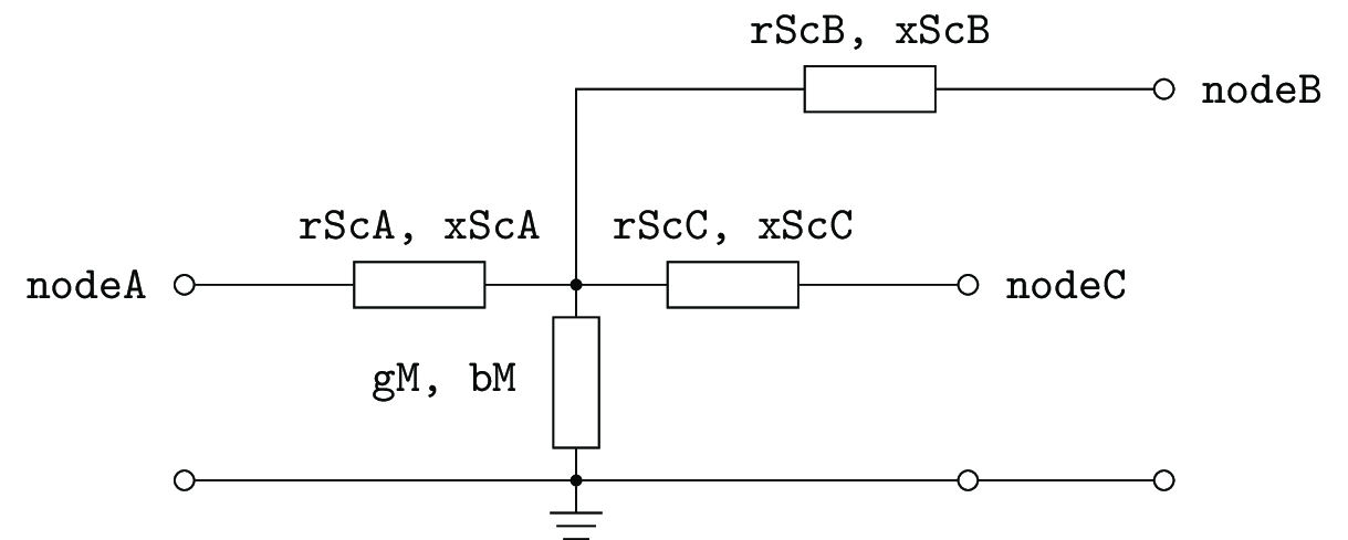
“Star like” T-equivalent circuit diagram of a three winding transformer
Attributes, Units and Remarks
Type Model
All impedances and admittances are given with respect to the higher voltage side.
| Attribute | Unit | Remarks |
|---|---|---|
| uuid | ||
| id | Human readable identifier | |
| rScA | Ω | Short circuit resistance in branch A |
| rScB | Ω | Short circuit resistance in branch B |
| rScC | Ω | Short circuit resistance in branch C |
| xScA | Ω | Short circuit impedance in branch A |
| xScB | Ω | Short circuit impedance in branch B |
| xScC | Ω | Short circuit impedance in branch C |
| gM | nS | No load conductance |
| bM | nS | No load susceptance |
| sRatedA | kVA | Rated apparent power of branch A |
| sRatedB | kVA | Rated apparent power of branch B |
| sRatedC | kVA | Rated apparent power of branch C |
| vRatedA | kV | Rated voltage at higher node A |
| vRatedB | kV | Rated voltage at higher node B |
| vRatedC | kV | Rated voltage at higher node C |
| dV | % | Voltage magnitude increase per tap position |
| dPhi | ° | Voltage angle increase per tap position |
| tapNeutr | Neutral tap position | |
| tapMin | Minimum tap position | |
| tapMax | Maximum tap position |
Entity Model
| Attribute | Unit | Remarks |
|---|---|---|
| uuid | – | |
| id | – | Human readable identifier |
| operator | – | |
| operationTime | – | Timely restriction of operation |
| nodeA | – | Higher voltage node |
| nodeB | – | Intermediate voltage node |
| nodeC | – | Lowest voltage node |
| parallelDevices | – | Amount of parallel devices of same attributes |
| type | – | |
| tapPos | – | Current position of the tap changer |
| autoTap | – | true, if there is a tap regulation apparent and active |
Caveats
Nothing - at least not known. If you found something, please contact us!
| [Gremmel1999] | Gremmel, H., Ed., Schaltanlagen. Cornelsen Verlag, 1999, Vol. 10, isbn: 3-464-48235-9. |