General Remarks on Participant Models
Reactive Power Characteristics
Reactive power characteristics are designed to describe reactive power control behaviour of the models. In Germany, system operators can require system participants to follow certain characteristics specified in the operators technical requirements and individually selected per connected asset.
Currently three different characteristics are implemented:
Fixed Power Factor
Active and reactive power are coupled by a time-independent power factor.
It can be parsed from cosPhiFixed:{(0.0, 0.95)} (exemplary).
Active Power Dependent Power Factor
The power factor is determined based on the current active power feed in or consumption.
The characteristic in the figure below would be described by the three coordinates (0.0, 1.0), (0.9,1.0) and (1.0, 0.95).
Alternatively it can be parsed from cosPhiP:{(0.0, 1.0),(0.9,1.0),(1.0, 0.95)}.
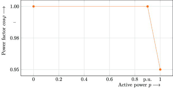
Exemplary active power dependent power factor
Reactive Power as Function of Nodal Voltage Magnitude
The reactive power is directly derived in accordance to the nodal voltage magnitude.
The characteristic in the figure below would be described by the three coordinates (0.92, -1), (0.97, 0.0), (1.03, 0.0)
and (1.08, 1.0).
Alternatively it can be parsed from qV:{(0.92, -1),(0.97, 0.0),(1.03, 0.0),(1.08, 1.0)}.
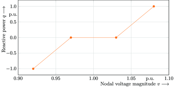
Exemplary reactive power as function of nodal voltage magnitude